 da
da de
de es
es fr
fr it
it nb
nb nl
nl pt
pt sv
sv fi
fiFord Focus 2 Instrument Cluster
A vehicle with trouble starting or that does not start at all, because of a defective instrument cluster. This may sound a bit odd for the layman, but it could in fact be the case. The electronics in today’s modern cars are so dependent on each other that one single failing component can cause problems. Signals that were sent to the ECU through the instrument cluster do not reach their target, with all the associated consequences.

A vehicle with trouble starting or that does not start at all, because of a defective instrument cluster. This may sound a bit odd for the layman, but it could in fact be the case. The electronics in today’s modern cars are so dependent on each other that one single failing component can cause problems. Signals that were sent to the ECU through the instrument cluster do not reach their target, with all the associated consequences.
You might only expect this problem for the more expensive and luxurious cars, considering that they are overloaded with electronics, but it could also occur with ‘‘everyday’’ cars like the Ford Focus. The second model from the Focus series, the DA2, indeed sends relevant information through the instrument cluster. When this cluster does not function, the car might not respond to the accelerator or in the future not even start anymore. Fortunately, this rarely happens. In case your car does not start, a good slap on the dashboard might (temporarily) help.
What goes defective in most cases?
The Ford Focus 2 instrument cluster frequently suffers from problems but with most of them the car is still able to start. One or more needles might drop to zero, the display lighting might switch off and various CAN errors like error code U1900 frequently occur. But what goes defective in the cluster in such cases?
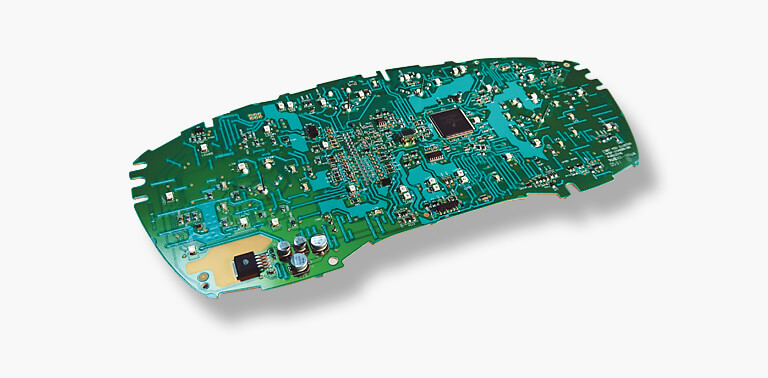
The story is broadly in line with that of the Volvo instrument cluster. There are small networks with resistances everywhere on the Printed Circuit Board (PCB). Cracks in those networks cause various complaints including failing elements. These networks have complex structures, so it requires thorough research to identify the problem and the affected features. Cracks might also occur in buried vias (internal connections in the circuit board) which makes it even harder to find the defect. In addition, we sometimes see that the processor does not connect to the circuit board on every point. You can imagine that in such case the processor does not function like it should.
Remanufacturing: the process
The remanufacturing process involves a lot of testing and making diagnoses. It took us quite some time and research to figure out and use the incoming CAN messages, but this has left us better able to control and test each feature separately. We have our own Vision comprehensive test setup that allows us to control everything on command. Still it was quite a challenge to make all the features testable. This instrument cluster uses namely two different CAN buses: one with a speed of 125kbps (mid-speed) and the second one with a speed of 500kbps (high-speed). Some features depend on more signals than just the CAN messages. There is a lot involved when it comes to checking all the features.
Defects that become visible during this comprehensive entry test are compared to the complaint, which should match. Often more defects are found than initially mentioned, which is however no problem since every cluster follows the standard remanufacturing process. Every weak element is taken care of, which shows the big difference between repairing and remanufacturing. Therefore, for remanufacturing itself it does not really matter what is defective and what is not. The following items are always checked for defects:
- Power supply and mass
- The 5V circuit
- All the LED lights of the instrument cluster, including those from the display and the needles
- Functioning of CAN HS and CAN LS (500kbps and 125kbps)
- Transmittance of various signals through the CAN buses (RPM, speed, cooling water temperature, etc.)
- Transmittance of various signals outside the CAN buses (accelerator pedal signal, tank contents)
After all problems have been localised, the glass is removed and the needles are gently detached. Next up is specialist soldering. We will not get into too much detail, but one must be extremely careful around those fragile components. The processor might namely become overheated or suffer from short circuit. The places were buried vias became defective, bypasses are created.
Once all the weak elements have been taken care of, the unit can be reassembled. But then, how do you put those needles back into their correct position? To solve this challenge, we programmed our Vision test setup in such a way that the needles can be temporarily locked in a certain position, like 62 mph and 4000 rpm. Putting the needles back in their right positions therefore becomes a lot easier.
Certainly, we do not return the cluster before thoroughly testing it once more. After this final test the glass is carefully reassembled and our Logistics Department takes care of the further process.
The Ford Focus 2 instrument cluster in detail
The Ford Focus dashboard may seem simple at first glance, but the digital display between the analogue-looking gauges actually tells us that it concerns a modern instrument cluster. Even though some functions appear to be analogue, in fact they are not. The needles of the gauges move because of stepper motors, which receive their signals from the processor. These signals usually originate from various CAN messages that were sent, sometimes more than a hundred times per second. Just one plug connects the cluster to the rest of the car. Analogue speedometer cables have become quite outdated.
Looking at the plug in more detail, it immediately becomes clear that no less than 32 pins are used. Why does this cluster use so many pins when a CAN is also used? Are not all CAN messages sent through two channels? Like we already explained, this instrument cluster is connected to multiple components. Next to the regular connections for Vcontact, Vbattery and mass, the cluster also receives separate signals that were not sent through CAN. We will give a few examples.
- One of those signals that are sent through a separate channel, is a resistance signal coming from the electronic accelerator pedal. This signal is received by an independent pin and converted to a CAN message, enabling the signal to become useful for the Powertrain Control Module (PCM). Therefore, the PCM is completely dependent of the instrument cluster: when the cluster fails, there is no signal from the accelerator pedal. You can press the accelerator pedal as much as you want, but nothing will happen…
- Another pin is specially reserved for managing the cluster lighting. This lighting is fully comprised of LED lights and obtains power from the lighting switch. Once the lighting (e.g. headlights) is switched on, the cluster lighting also turns on. The dimming function is controlled by the lighting switch itself.
- There are 3 pins in use that can be connected to the mass once the menu in the cluster is operated by using the buttons on the steering column switch. Controlling these buttons produces a short signal to the processor that in turn changes the menu on the display.
- We would almost forget that not 1, but 2 CAN buses are used, resulting in 2 pins for the mid-speed CAN and another two for the high-speed CAN.
The message is probably clear: in this brief story we explained 12 pins that all have their own function and we only described a small part of all the features. Therefore, it is not difficult to get to 32 pins in a multifunctional cluster like the one of the Ford Focus 2. CAN might have become an indispensable component in modern cars, it is surely not complete and comprehensive enough. The usage of separate signals will keep existing.
However, specialists would also like to know which pins are connected to the functions described above? We made a short and practical list:
- Pin 06 = Mass
- Pin 04 = 12v Vcontact
- Pin 09 = Cluster lighting
- Pin 17 = CAN(1)-L (500kbps)
- Pin 18 = CAN(1)-H (500kbps)
- Pin 22 = CAN(1)-L (125kbps)
- Pin 23 = CAN(1)-H (125kbps)
- Pin 32 = 12v Vbatt
Much remains to be told about the processor, the memory and the CAN, but we have already written an extensive article about a Volvo instrument cluster in which these topics are explained. We recommend reading it to anyone interested in CAN and CAN messages. The article can be found here.
Finally, there is one practical tip we would like to mention: An unfortunate phenomenon with modern electronics is that it secretly keeps using electricity after it seemed to be switched off. This might also occur with the instrument cluster of the Ford Focus 2, which uses 0,06 mA in stand-by mode and about 0,7 mA when switched on. In case you would like to measure if the cluster secretly uses electricity, these values can be used as a reference.
Disassembling the unit
Pay attention! We know from experience that the glass of the instrument cluster easily breaks during disassembly. The cluster is properly attached to the dashboard and too much tension or pressure on certain spots might cause fractures or cracks in the glass: Ford Focus II 2005-2010. This one is visible, as soon as you are logged on.
Disassembling the cluster is relatively easy but be careful. First, pull the (clicked) upper cover that connects the steering column to the dashboard. Once removed, two Torx screws become visible that hold the cluster. Remove the screws but do not pull the bottom yet. It is namely wiser to start at the upper side, where the instrument cluster is clicked onto the dashboard on multiple points. Releasing will be easier by pushing something between the cluster and dashboard (for which there are also special tools), but be careful for the glass not to break and for damaging the dashboard. Once released, the last thing to do is disconnecting the plug at the back.