 da
da de
de es
es fr
fr it
it nb
nb nl
nl pt
pt sv
sv fi
fiInstrument Cluster Volvo S60, V70, XC70, S80, XC90 1998-2009

Through the years, Volvo has successfully been using its spotless reputation. The Swedish car brand has always been committed regarding safety, and a car that is safe should also be solid, right? At least, that is what most people think. The design of many Volvo cars underlines this, which is always tranquil and sound. Exuberant Italian designs were not Volvo’s thing, until recently.
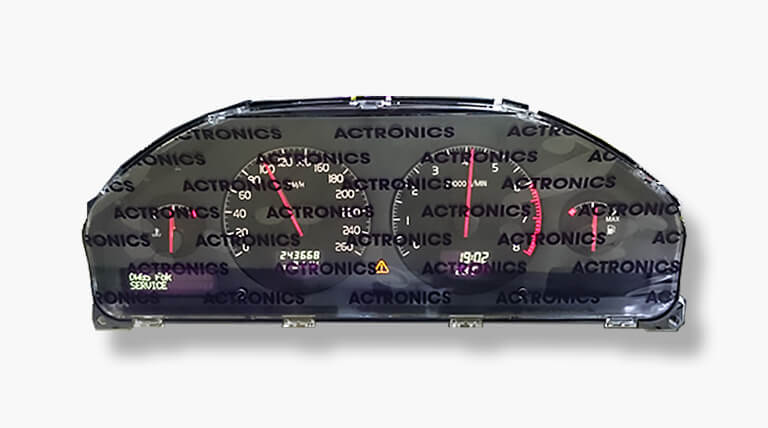
The same goes for the interior. The dashboard layout has a calm and clean design. The instrument cluster looks organised: four analogue-looking gauges with four almost unobtrusive displays beneath them. One gets the feeling that everything will keep functioning forever and when not looking at it, there are no elements trying to get your attention. A Volvo is actually a perfect transport vehicle to relax in after a day of hard work.
Even though the following might surprise some, also a Volvo can suffer from failures. Underneath the cleanly designed dashboard there are many electronics that almost entirely rely on the incoming messages from the Controller Area Network (CAN). Which in turn means that the instrument cluster is equipped with a flash memory, EEPROM and processor. The simple analogue needles in the instrument cluster are in fact not analogue at all: incoming CAN messages are transformed in a value that determines the needle’s position. Looks can be deceiving, because there is a hive of activity going on in the dashboard and the operating electronics are certainly not indestructible.
What goes defective in many cases?
The complaints we often see have mostly to do with the failure of one or more features. Even a complete failure of the dashboard might occur. In such cases it was not always easy to identify the cause, but nowadays we are able to do much more due to our own developed test equipment and custom CAN files. We now know that the Volvo instrument cluster only switches on after multiple specific CAN messages are received. Therefore we know exactly which messages we should send in order to get the cluster to work and to find the cause of the problem. This would otherwise be impossible.
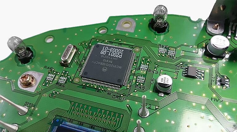
But for what reason do some elements become defective? Multiple small networks with resistances surround the processor. Cracks in these networks cause various complaints, including the failure of certain elements. These networks have complex structures, it therefore requires thorough research to find the problem. We regularly see that the processor does not connect to the circuit board on every point. One might imagine that in such cases the processor does not function like it is supposed to.
Besides failing elements, it now and then occurs that the buttons for resetting the day counter or setting the clock do not function anymore. Also the speaker for the signals might malfunction. We replace all these components with ones of higher quality.
Remanufacturing: the process
At ACtronics we strive for quality. It would be easy for us to just repair the found defects and then return the unit, but that is not how we conduct our business. Every instrument cluster that enters our building follows a standard process in which every weak element is handled, whether it is defective or not. Besides, we do not look for solutions that solely solve the problem, but that actually improve the product.
Remanufacturing instrument clusters involves a lot of testing. We want to be absolutely certain that every feature functions like it should. That is why we examined every CAN message in detail, so we can send a message to the cluster for really every feature. When the cluster responds, we know this feature functions properly.
At the final check we are also strict. The instrument cluster should keep functioning even when we slightly bend the circuit board and vary the voltage from 10V to 16V. When everything seems to be in order the glass is assembled. This is not the original glass but a new one. Therefore the quality is not only on the inside but is also shown on the outside: when the cluster is delivered it has a new look.
Did you know?
The Volvo cluster and the climate control with this type of dashboard are supplied with voltage from the same relay. In case you experience that both fail, first check if the 5 Pin relay is in order. When the dashboard still does not work it would be our pleasure to remanufacture it for you.
The instrument cluster in detail
The dashboard may seem pretty straightforward: 4 needles, 2 displays with lights and 2 displays with some simple information like the clock. How could the underlying technology be complicated?
But everything is not as it seems. The needles of the different gauges are not managed by a resistance value or in an analogue way, but receive all their information through the CAN. Once you see the word ‘CAN’, you immediately know that a processor and a memory are involved to show the different kinds of information. All the raw data enters the dashboard through a CAN message. The message says what it is meant for and also contains a certain value. In some cases this value is directly shown in the display, in others it is first calculated.
To give everybody some insight in the world of CAN messages and how the instrument cluster can use them for calculations, we show an example:
29 0360424C 0 8 — 60 00 00 00 0C 75 01 00
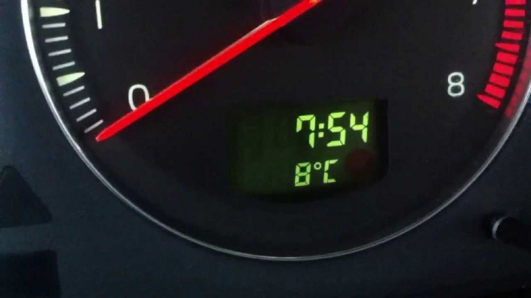
Above an example of a CAN message is shown. For many it may seem like a code word, but this is the language the electronics in the car nowadays speak. Let’s assume for the sake of convenience that the first part shows us that this message is meant for the 24-hour clock. The second is part is way more interesting, this is the part where many things change.
Every piece of 2 ‘‘numbers’’ in the second halve is called a digit or a nibble, so the message contains a total of 8 digits. When we start counting, we always start with D0. Digit 5 and 6 are therefore automatically D4 and D5. Once the clock changes time, we see these two digits changing. So this is where the clock is hidden.
But which code represents what time? In order to find out, you must first know that the numbers in CAN messages are hexadecimal: instead of sequences from 0 to 9 they go from 0 to F. The 6 extra letters after 9 enable you to count until 16 instead of 10. In addition, you must keep in mind that every change in the clock (therefore also in programming language) refers to minutes.
So the code OC 76 shows 1 minute later than the now shown OC 75.
But despite of this knowledge we are not there yet. According to our theory, code OC 75 means:
(0*16³)+(12*16²)+(7*16¹)+5= 3189 minutes?!? The clock shows 19:01…
Even when converting the shown time (19:01) to absolute minutes, you will not get to 3189. However, the theory is correct: afterwards it seemed that value 08 00 is value zero of the clock. When it is 00:00, the hexadecimal counting starts at 0800, which represents 2048 minutes.
Let’s put this to the test: we want the clock to show 14:27. First, we convert this into the amount of minutes: 867. Next, we add the zero value: 867 + 2048 = 2915. Then we convert this value into a hexadecimal value: B63 (the code becomes 0B 63). We replace OC 75 in the CAN message with OB 63, and then… the clock shows 14:27. It really works!
We can conclude that the instrument cluster is able to read CAN messages and subsequently immediately shows them or first performs calculations and then showing the outcome. The processor performs these calculations and the memory contains clear information on how every message should be handled. This cooperation is essential and a malfunction between or in these components might cause a complete failure or disruption of the dashboard.
But why choose for a CAN, when they are so sensitive to interferences? All the data can be send through one single cable (the cluster has only one plug) and the possibilities for calculations and displays are infinite. A CAN is simply way more functional than the old-fashioned heavy cable looms.
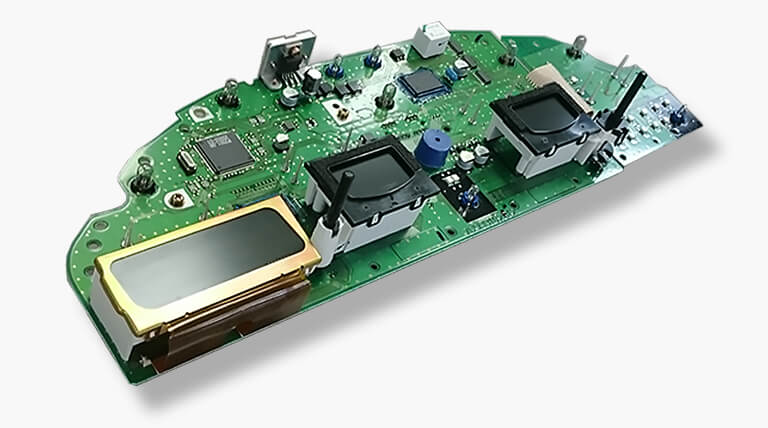
Disassembling the cluster
Disassembling the cluster is relatively simple. First remove the plastic edge that is clicked around the instrument cluster. Sometimes two T25 Torx screws are used on the upper side. In case they are not there, you can immediately pull the upper side towards yourself and after that also the bottom. You will notice that the bottom is assembled to the upper cover of the steering column. After quarter turning the steering wheel, there will be enough space to remove it in one movement. Once removed, 4 T25 Torx screws become visible that attach the cluster to the dashboard. Unscrew these one by one and gently pull the cluster. The wiring is connected in one central plug, on the middle of the back of the cluster.